Skip to Content

Tag Archive: cnc manual

  1. Spoil Boards, Hold-downs, and Dust Collection

    Comments Off on Spoil Boards, Hold-downs, and Dust Collection

    Holding the part to be cut firmly and without movement or vibration is often the biggest challenge faced when cutting on a CNC. Chatter, movement, premature tool wear, tool breakage, poor edge finish, and chipping are the result of inadequate hold-down. How well you can hold the part is perhaps the biggest factor in how fast you can cut.

    There is a lot of information on building dedicated spoil boards and jigs so we cover the basics in our free downloadable CNC Manual, and will provide an excerpt here. For the rest of the article, refer to the CNC Manual pages 13, 14, 15.

    Some factors to consider include:

    • Some CNC operations are best suited to using flow through or suck through vacuum systems. Particularly well-suited for cutting large parts and sheets of material, these types of routers utilize replaceable spoil boards—so called because they are underneath the material to be cut and are cut and “spoiled” during machining. The spoil board can then be resurfaced and used again, sparing the router table underneath from damage. These types of systems are easy to use and require minimal maintenance. Using low (LDF) or medium density fiberboard (MDF), both sides are machined level using a large “fly” cutter to remove any imperfections or coatings. Vacuum is evenly distributed to the entire surface of the table. Air loss from the sides can be minimized by using rubberized or latex paint. Areas not to be used should be sealed with sheets of laminate, plastic, or other non-porous materials. Grooves resulting from the cutting process can cause vacuum leakage when cutting a variety of patterns. Resurfacing the spoil board should be done regularly.

    • Smaller or more intricate parts are better suited to dedicated spoil boards due to vibrations and part movements. Cutting small parts can be challenging since a larger volume of air is lost due to the number of channels cut between parts. As more parts are cut, more air pressure is lost, resulting in vibration and part movement.

    • Leaving a thin skin (onion skin) or programming tabs at certain points can help to hold small parts together but require a secondary routing or sanding operation.

    • Use dedicated spoil boards for recurring part runs. Taking the time to make a proper spoil board will pay for itself by allowing faster feed rates, giving you a better finish, and prolonging tool life.

    To continue, refer to the CNC Manual pages 13, 14, 15.
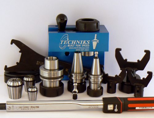
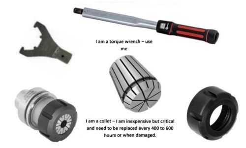
  2. CNC Routers: Things to Avoid

    Comments Off on CNC Routers: Things to Avoid

    Understanding the different variables involved in CNC routing can be overwhelming, especially to anyone new
    to CNCs. That is why Edge of Arlington Saw & Tool is here to help you in selecting the proper tool for the job.
    Don’t let the complexities involved keep you from maximizing tool life, machine time, and profits—help is only
    a phone call away.

    Dead stops, also known as “dwelling in the cut,” can lead to premature tool wear and failure. When
    changing directions of travel or when cutting small pieces, a one second stop at 18,000 RPM generates
    enormous heat and no means of extraction. Imagine rubbing your hands together 300 times per
    second—a sure way to form a blister. This is more of a machinery and software issue. Certain
    programming techniques can help to compensate, such as ramping, use of loops at sharp outside
    corners, and the use of exit ramps.

    Plunge cutting. While this is the oldest and most widely used method of entering the material, it is not
    always the most efficient. Plunge cutting can lead to chips wrapping around the router bit after
    repeated plunges. Whenever possible you should Ramp into the cut. This eliminates the heat
    generated during the plunging process and can eliminate burn marks at the plunge point. Plunging can
    also cause the bit to “walk” because there is no centering point—this will be evident as ovals, holes,
    and entry points larger than the diameter of the tool. If you cannot ramp in, a good alternative is to
    plunge down outside of the workpiece and enter from the side. Spiraling in can also help. Whatever it
    takes to keep the router bit moving.

    Routing holes is never the optimum choice. Use drills for drilling, routers for routing. Drills turn at
    much lower RPM than routers do. Router bits generate too much heat when drilling. Drilling just a
    couple of holes per sheet will significantly reduce the life of your tooling. In fact, you will dull more
    drilling the two holes than cutting the entire piece. If you do not have drill heads to take advantage of
    European type boring bits, turn the RPM down as low as possible, 4,000-5,000 RPM at most, and
    plunge as fast as possible. An upshear will help to remove the chips if hold-down is not a problem. On
    deep holes “pecking” can sometimes help.

    Small parts and scrap pieces can become projectiles if left after the cutting process without sufficient
    hold-down. They can also be sucked into the dust collector and cause a blockage. Skin cutting and the
    use of tabs can help to hold small parts.

    Over tightening of the collet and collet nut is a common mistake. Most operators assume that the
    tighter the better—this is not true and can lead to premature tool and collet wear and tool breakage.
    Collets are the most misunderstood and overlooked part of the CNC, often the cause of poor finish,
    short tool life, and unnecessary machine wear. Collets are made of spring steel and are subject to
    distortion when put under undue pressure. It is highly recommended that collets be tightened to
    manufacturers’ specifications with the use of a torque wrench.

    Fires—yes it happens. A tool left in the same place for enough time can and will start a fire. It is
    important never to leave a CNC running without an operator. You wouldn’t believe how fast things can
    go wrong. The dust collection system and the vacuum system will aid in the fires speedy travel. If this
    ever happens to you, beware of flash-back when the vacuum is turned off. When it is safe to do so, it is
    important to remove and examine the bleeder board and table underneath, as embers can remain and
    once again flair up.

    For more, download our free CNC Manual.

  3. Climb Cut vs. Conventional Cut

    Comments Off on Climb Cut vs. Conventional Cut

    CNC Manuals

    Climb and conventional cutting refer to the direction of travel in relation to spindle rotation. In the case of a right-hand rotation spindle, climb cutting (clockwise direction) can produce a different result than conventional cutting (counterclockwise direction).

    • In many circumstances conventional (CCW) cutting will provide the best finish, especially in plastics and with larger diameter tools. If the scrap piece has a better finish than the finished part, a change in cutting direction will provide you with the opposite results. Don’t be afraid to experiment with cutting directions or have different cutting directions on the same workpiece.

    • There are also left-handed tools and holders available for left-hand rotation—climb cutting would then become counterclockwise and conventional cutting would become clockwise.

    • When cutting the interior of a part as opposed to the outside perimeter, conventional cut becomes climb cut and vice versa.

    • When cutting two parts with one pass such as when cutting parts that are nested or mirrored, keep in mind that one side of the cut will be conventional cut and the other will be climb cut.

    • Climb cutting is more aggressive and can move small parts.

    • When cutting hard materials and metals such as aluminum, climb cutting is preferred.

    CNC-MANUAL-PDF-Nov-2022

    EOA CNC MANUAL 2018

  4. Tips to Safely & Efficiently Prolong the Life of CNC Tooling

    Comments Off on Tips to Safely & Efficiently Prolong the Life of CNC Tooling


    Dead stops, also known as “dwelling in the cut,” can lead to premature tool wear and failure. When changing directions of travel or when cutting small pieces, a one second stop at 18,000 RPM generates enormous heat and no means of extraction. Imagine rubbing your hands together 300 times per second – a sure way to a blister. This is more of a machinery and software issue. Certain programming techniques can help to compensate, such as ramping, use of loops at sharp outside corners, and the use of exit ramps.
    Plunge cutting, while this is the oldest and most widely used method of entering the material, it is not always the most efficient. Plunge cutting can lead to chips wrapping around the router bit after repeated plunges. Whenever possible you should Ramp into the cut. This eliminates the heat generated during the plunging process and can eliminate burn marks at the plunge point. Plunging can also cause the bit to “walk” because there is no centering point; this will be evident as oval holes and entry points larger than the diameter of the tool. If you cannot ramp in, a good alternative is to plunge down outside of the workpiece and enter from the side. Spiraling in can also help; whatever it takes to keep the router bit moving.
    Routing holes is never the optimum choice. Use drills for drilling, routers for routing. Drills turn at much lower RPM than routers do; router bits generate too much heat when drilling. Drilling just a couple of holes per sheet will significantly reduce the life of your tooling; in fact, you will probably dull more drilling the 2 holes than cutting the entire piece. If you do not have drill heads to take advantage of European type boring bits, turn the RPM down as low as possible, 4-5000 RPM at most, and plunge as fast as possible, an upshear will help to remove the chips if hold down is not a problem. On deep holes “pecking” can sometimes help.
    Small parts and scrap pieces can become projectiles if left after the cutting process without sufficient hold down. They can also be sucked into the dust collector and cause a blockage. Skin cutting and the use of tabs can help to hold small parts.
    Collets & Torque WrenchesOver-tightening of the collet and collet nut is a common mistake. Most operators assume that the tighter the better – this is not true and can lead to premature tool and collet wear and tool breakage. Collets are the most misunderstood and overlooked part of the CNC, often the cause of poor finish, short tool life, and unnecessary machine wear. Collets are made of spring steel and are subject to distortion when put under undue pressure. It is highly recommended that collets be tightened to manufacturers’ specifications with the use of a torque wrench
    Fires, yes it happens. A tool left in the same place for a sufficient amount of time can and will start a fire. It is important never to leave a CNC running without an operator; you wouldn’t believe how fast things can go wrong. The dust collection system and the vacuum system will aid in the fires speedy travel. If this ever happens to you, beware of flash-back when the vacuum is turned off. When it is safe to do so, it is important to remove and examine the bleeder board and table underneath, embers can remain and once again flair up.

    Check out our free CNC Manual available at EOASAW.com!

    You may also be interested in reading other excerpts from our CNC Manual: Router Bit Tool Geometry, Tool Materials and Their Uses, Factors To Be Considered Before Selecting Your Tool, and Collets & Tool Holders Maintenance.

  5. Router Bit Tool Geometry

    Comments Off on Router Bit Tool Geometry

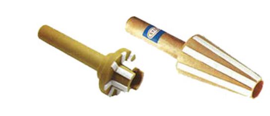
    There are a lot of different geometries involved in making a router bit—clearance angles, grinding angles, hook angles, axle angles, side clearance angles, radial clearance angles, and side rake. For the purposes of our discussion we will only talk about the basics.

    • Tool size is a determining factor in how fast you can cut and what types of geometries and clearance angles are possible—all major factors in productivity, finish, and consistency of parts.
    • For stability, choose the shortest cutting length possible. You should have sufficient shank to fill 80% of the collet. Longer router bits will deflect more—run-out is more exaggerated the longer the tool.
    • The larger the diameter of the tool the faster you can go—up to a point. While a 3/4” diameter bit will be able to handle a much larger chipload than a 1/8” diameter bit, larger bits require slower speeds for safety reasons. The following are general safety guidelines:
      • Up to 1” Diameter—Maximum of 24,000 RPM
      • 1” to 1-1/2” Diameter—Maximum of 18,000 RPM
      • 1-1/2” to 2-1/4” Diameter—Maximum of 16,000 RPM
      • 2-1/4” to 3” Diameter—Maximum of 14,000 RPM
      • 3” to 3-1/2 Diameter—Maximum of 12,000 RPM
    • Use the largest shank possible. However, cutting diameters smaller than the shank diameter cause stress points at the transition and can contribute to breakage. Solid carbide tools larger than 1/2” in diameter can be expensive and are designed when extra long lengths are needed. The following are safety guidelines with relation to shank size and head diameter:
      • 1/2” diameter shank—Maximum large diameter is 2”
      • 1/2” diameter shank—Maximum small diameter is 1/2”
      • 1/2” diameter shank—Maximum overall length is 4”
      • 5/8” diameter shank—Maximum large diameter is 3”
      • 5/8” diameter shank—Maximum small diameter is 5/8”
      • 5/8” diameter shank—Maximum overall length is 4-1/2”
      • 3/4” diameter shank—Maximum large diameter is 3-1/4”
      • 3/4” diameter shank—Maximum small diameter is 5/8”
      • 3/4” diameter shank—Maximum overall length is 5”
    CNC Manual

    Free CNC Manual

    We cover this topic in more detail in our free to download CNC Manual.


    For more, refer to our CNC Manual. 

    To peruse our online catalog or to place an order, visit EOASAW.com or call us at 817-461-7171.

    Have any questions? Feel free to ask us in the comment section, give us a call, send us an email, or visit us on Facebook!

    For more informative EOASAW blog posts, visit our main Blog Page.

  6. Tool Materials And Their Uses

    Comments Off on Tool Materials And Their Uses

    Our free CNC Manual will guide you through selecting the right tool, maximizing machine time, finish, tool life & profits. Here we talk about tool materials and their uses.

    • High speed steel (HSS). Used primarily on soft woods such as pine, aluminum, and soft plastics. HSS can be sharpened to a very sharp edge and at the appropriate hook and clearance angles “slices” through soft material, reducing pre-splitting. HSS is more impact resistant than carbide but is not wear resistant enough to hold up to many of today’s man-made materials.
    • Tangtung (TG) A cast alloy material with a high tungsten content. Tangtung retains its hardness at very high temperatures, is more shock resistant than carbide, and resists corrosion from wood acids. Tangtung, like HSS, can be sharpened to a fine edge and is primarily used in hardwoods for a superior cross-grain cut. TG can and has been used in insert tooling for CNC applications. Freeborn Tool has a line of insert shaper cutters available in Tangtung. Tangtung is never recommended for manmade fiber boards or plywood.
    • Carbide-tipped (CT). Used primarily on hard woods, laminates, composite materials, and for abrasive or resin-based products. Carbide is welded or brazed onto a steel body and profiled to the desired pattern; therefore it is the most common type of material used for profile and custom tooling. There are many different grades of carbide. The harder the grade of carbide, the more likely it is to break during the heating and cooling process in manufacturing—problems overcome with insert tooling.
    • Solid carbide (SC). Used primarily on hard woods, wood composites, laminates, plastics, aluminum, and other composite materials for longer life and faster feed rates. Solid carbide can be cast into just about any shape. Solid Carbide rods are well-suited for making router bits with spiral geometries and small form or profile tools. Solid carbide blanks are also well-suited for insert tooling and are available in many standard sizes and configurations. Solid carbide is very wear resistant but not impact resistant—strain and deflection often lead to tool breakage.
    • Diamond (PCD). Polycrystalline diamond is primarily used on composite materials such as melamine. PCD diamond is extremely heat and wear resistant (100+ times carbide) but is not impact resistant, and in fact, it chips fairly easily. Materials must be free of all foreign matter and be homogenous in nature or tool damage may result. Machine condition and maintenance are vital to cost effectiveness. High initial cost but very low operating cost can make diamond tooling a very economical alternative. Diamond wafers are brazed on to a steel body and are not suited to small sizes.
    • Insert tooling. Insert tooling can provide consistency in production. Using replaceable inserts instead of brazed-on-carbide allows you to maintain a constant diameter. Insert tooling is also able to utilize harder, more wear resistant carbide than traditional CT tooling. While very versatile in nature, the design does not lend itself well to small diameters due to the need to affix the insert with Gibbs and/or screws.

    You may also be interested in reading our post on Factors to be Considered Before Selecting Your Tool.


    For more, refer to our CNC Manual. 

    To peruse our online catalog or to place an order, visit EOASAW.com or call us at 817-461-7171.

    Have any questions? Feel free to ask us in the comment section, give us a call, send us an email, or visit us on Facebook!

    For more informative EOASAW blog posts, visit our main Blog Page.


  7. Factors To Be Considered Before Selecting Your Tool

    Comments Off on Factors To Be Considered Before Selecting Your Tool
    CNC router accessories

    CNC Router Accessories

    Many factors need to be considered when evaluating any cutting situation, before selecting a tool. You can find more useful information in our FREE CNC Manual available for download on our site!

    • What is the desired finish? Chip-free, hidden part, some minor chips ok, etc. Are both sides (top, bottom) of material of equal importance? The desired finish will often dictate not only what type of tool we can use but also how fast we can cut and whether we must make multiple passes.
    • Which is more important, speed or finish? While striving for both, sometimes we must assign priorities or make compromises. Higher quality finish can mean higher machining costs (multiple passes, use of more expensive tooling, slower feed rates, etc.). However, ironically, most people run their tools at too slow a feed rate at too high of a RPM, resulting in heat buildup and premature tool wear.
    • What are the machines capabilities and limitations? It is important to know your CNC’s capabilities and limitations. If your machine’s top feed speed is 600 IPM as opposed to a machine capable of feed speeds of 1200 IPM, your tool selection and setup will be quite different. It is important to note here that just because your machine is capable of running at 3400 IPM does not mean you can cut at that rate. When programming any cut for the first time, it is important to ascertain at what feed that part is to be cut. Part size or geometry alone may preclude you from running more than a few hundred IPM.
    • Do you have sufficient ability to hold the material you are cutting? If you can’t hold it, you can’t cut it. This is one of the most common problems that I encounter. I am continually amazed how many people will accept minimal feed rates and quality because of chatter and movement. Your ability to make a clean fast cut is related to your ability to hold the material firmly without vibration. Insufficient hold-down can be responsible for everything from premature tool wear and breakage to sub-standard parts, chatter marks, chipping, and material movement. A little planning and effort will give you huge payoffs in productivity and cost savings. When purchasing a CNC router, don’t skimp on the vacuum system. I have never met anyone who said they had too much.
    • What is the material you are cutting? Raw particle board, plywood, MDF, single-sided laminate, double-sided laminate, etc. Different materials have different cutting properties and may restrict your tool selection and will often dictate geometries, feed, speed, etc.
    • Are there any operations after this one that will cover, conceal, or change the shape of the part being cut? For example, the top edge will be rounded over or the edge will be covered in such a manner so that a small chip would be of no importance.
    • Is exact size important? Does another part rely on the accuracy of this part? Maintaining exacting measurements may require multiple passes after a tool is serviced or if the size is non-standard. Edge of Arlington offers insert and diamond tooling designed to solve these types of problems.

      Free CNC Manual

      Free! CNC Manual

    • Part configuration and size are important considerations. Small parts can be hard to hold. Intricate parts, parts with holes, curves, and short cuts can be challenging due to heat generated because of a machinery’s inability to make instantaneous speed and directional changes. Advances in machine capabilities have greatly improved the speeds associated with travel time and the ability to change direction. However, a bit turning at 18,000 RPM still turns at 300 inches per second and a good Boy Scout can start a campfire with a stick at a much lower RPM.


    For more, refer to our CNC Manual. 

    To peruse our online catalog or to place an order, visit EOASAW.com or call us at 817-461-7171.

    Have any questions? Feel free to ask us in the comment section, give us a call, send us an email, or visit us on Facebook!

    For more informative EOASAW blog posts, visit our main Blog Page.

  8. Collets & Tool Holders Maintenance

    Comments Off on Collets & Tool Holders Maintenance

    Collets and Torque Wrenches

    Collets & Torque Wrenches

    One of the most critical and most over-looked parts of the CNC router is collet and tool holder maintenance issues

    Collets and tool holders are critical parts of any CNC; they should be thoroughly cleaned and inspected during every tool change. Collets are inexpensive and expendable, especially compared to the cost of the tooling that relies on its accuracy.

    Edge of Arlington carries Techniks collets and holders and parts. Guaranteed accurate.

    Collets are made out of spring steel and should be replaced at least every six months of daily use (400-600 hours of run time), or when there is any sign of wear or damage.

    Tools should be tightened with the aid of a torque wrench. Over-tightening can cause distortion and runout, leading to tool wear, breakage, and finish degradation. Under-tightening can lead to bit slippage and twisting in the collet. Torque wrenches should only be used to tighten; using a torque wrench to loosen a nut can lead to miscalibration.

    When using full grip collets, whenever possible the tools should be chucked to fill 80% of the depth of the collet. Fillers are available to prevent collet collapse in the event the 80% rule cannot be maintained. Full grip collets have slits running from the top and bottom.

    Never chuck up on the cutting edge of the tool but always just below the fade of the flute.

    The tool holder is also subject to wear and should be inspected regularly for wear and damage. 

    Spindle wipers for collets

    Techniks Spindle Wipers

    Collet brushes are available for cleaning. Clean using a nylon or brass bristle brush only. Use alcohol after cleaning to ensure there are no chemical residues remaining.

    Spindle wipers are available for cleaning the spindle where the tool holder mounts. Real lambskin provides the best cleaning.

    Recommended torque is based on the style of collet used in the tool holder. An HSK tool holder for example is available with several collet options. Torque has been calculated based on the unique properties of each collet style.

    While changing the bit, it is important to use a set-up fixture or similar device to hold the tool holder safely. Damage to the tool, holder, or operator can occur if the holder is dropped or clamped improperly.


    Remember! Over-tightening can distort collets, causing runout problems and premature failure of the collet, tool holder, and cutting tool. Improperly tightened tool holders are a safety hazard. Always use a tightening stand and torque wrench to tighten collet nuts and pull studs.

    Cutting tools last longer when you … Torque it right!

    If you have a question, feel free to ask us in the comment area, or contact us and we’ll be happy to assist you. As well, we look forward to your comments! Thank you for reading.


    For more, refer to our CNC Manual. 

    To peruse our online catalog or to place an order, visit EOASAW.com or call us at 817-461-7171.

    For more informative EOASAW blog posts, visit our main Blog Page.